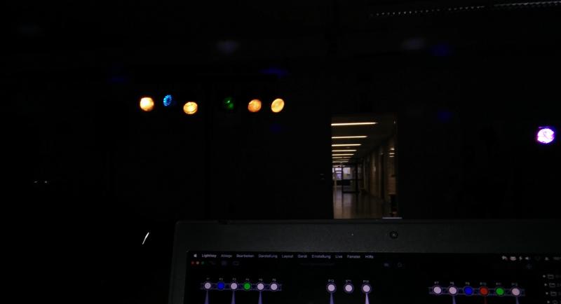
When I first joined the sound-and-lights team at my school, I was quite impressed by the amount of technical equipment they had. While I enjoyed sitting in front of the mixing console and setting up all the microphones and speakers, it was always the lights which caught my attention. We had twelve theater lights mounted on two crossbars with different colored filters in front of them. All those lights were powered by a small 24 channel DMX controller. Due to the powerful lamps we used (up to 1000 watts), turning on the lights regularly tripped the breaker. That’s why we had to use two separate 16 amp phases only to power the lights and a single one for the amplifiers (which also helped with the noise induced by the DMX light dimmers). I was always interested in computer-controlled stuff, so the natural thing for me was to look up how to control these lights with a PC. When I read about DMX interfaces and how they essentially only consist of a USB-to-UART and a RS-485 driver, I knew what my next project would look like.
How it works#
The basic principle of a DMX interface is pretty simple. Your PC sends out raw DMX frames over the USB interface, which are turned into serial data by a USB to UART chip. That data is passed onto a RS-485 driver that outputs differential signals. The DMX devices receive the signals with another RS-485 transceiver and their microcontroller uses the serial data to turn the lights on and off. The differential signaling used by RS-485 helps to reduce interference caused by noise and other cables running next to your DMX line.
I added some additional protection to prevent the USB ports from being fried by plugging in a faulty DMX device into your interface (some dodgy Chinese fog machines use XLR for their power supply, possibly putting mains voltage on your DMX bus). The necessary isolation is done using a DC-to-DC converter and an optocoupler for the data line.
First prototype#
The first experiments were done on a breadboard, but I quickly moved to more permanent prototype boards. I decided to integrate two independent DMX outputs to support more flexible routing options (like sitting in the middle of two DMX lights) and for an increased fail-safety. For the USB to UART conversion I chose a simple FT232 breakout board to help with soldering.
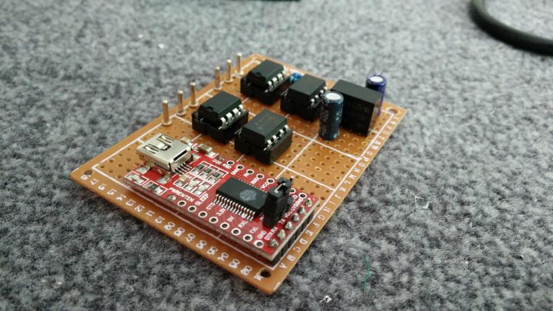
I like to do the connections between parts with very thin wires. The insulation burns off when touched with a soldering iron, making the soldering very easy and quick. I built many devices that way and the wiring has proven to be very reliable.
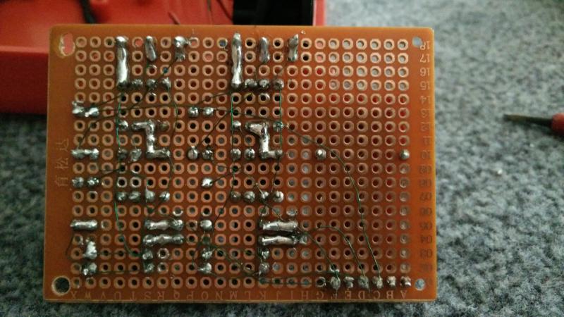
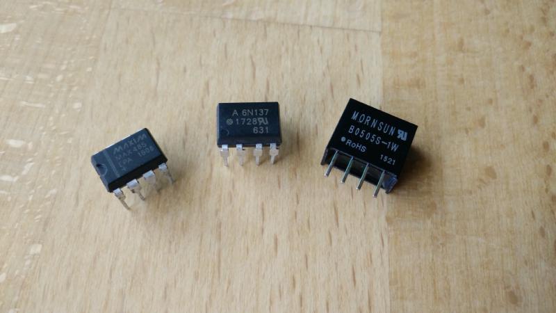
I used the following parts for this build:
- Maxim MAX485 (line driver)
- Vishay 6N137 (optocoupler)
- Mornsun B0505S-1W (DC-DC converter)
- FTDI FT232 (USB-UART converter)
- 120 Ω DMX termination resistor
- Current limiting resistor for the optocoupler
- Two capacitors for the DC-DC converter
All of the components are very cheap and readily available from Ebay or Aliexpress. The whole cost of this project was around €10-15 (the most expensive part being the enclosure).
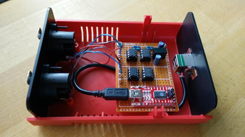
Final build#
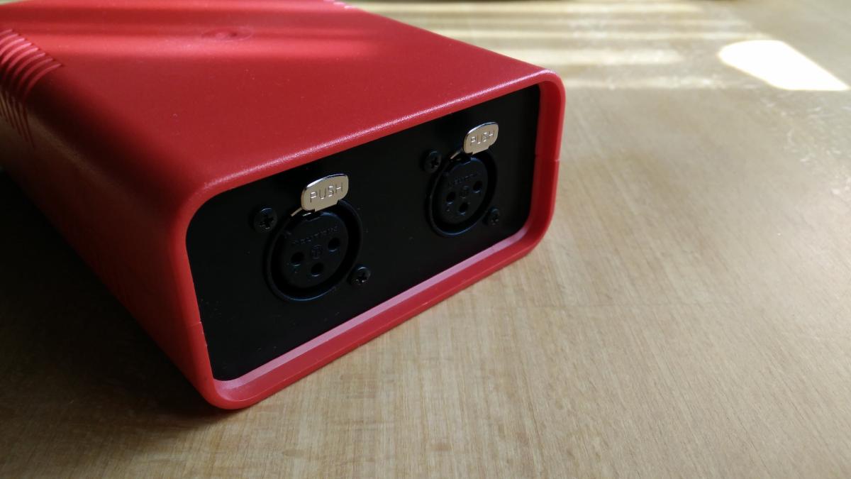
The assembled board was placed into a nice plastic enclosure, with two XLR jacks on one side and a USB type B connector on the other. Whether you choose good-quality Neutrik XLR sockets or some no-name Chinese ones is up to you. If you want to stick to the DMX specification you can of course also use the 5-pin versions. The USB jack was soldered to some copper angle brackets and screwed into the side. A simple mini USB cable with one end cut off was used to connect to the UART board.
The interface can be used with a whole range of software, such as DMXControl or Lightkey. The performance of the interface is limited by the power of your computer, because no internal buffering is done (this would require a microcontroller). Though any PC built in the last ten years should work just fine. I never had problems with dropouts or lights misbehaving.
The project was very fun to plan and build and enabled us to program some fancy light-effects and transitions. A few months later, the school decided to buy new LED lamps and a better lighting desk. Quite unfortunately, I didn’t have a chance to try out their new RGB lights with my interface because I already left school a few weeks after.