
A few weeks ago, my parents’ old Miele washing machine suddenly stopped functioning. It seemed like the machine finally required some maintenance, considering that it had been in operation for almost 20 years without issues. Disassembling the appliance revealed a number of hoses connecting the different parts of the washing machine. Upon closer inspection, several of these hoses were almost completely blocked by the detergent residue that had accumulated over the past two decades. After cleaning all hoses, the appliance initially seemed to be working fine again. However, at the end of the washing cycle, the machine didn’t start to spin up. According to multiple forum posts, this fault was most likely caused by the analog pressure sensor that determines the water level inside the drum. If the residual water doesn’t fall under a certain level during the pumping cycle, the machine aborts the current washing program. The white sensor housing can be easily spotted in the bottom right corner of the machine’s electronics board:

Following some quick measurements with a multimeter, I determined that the sensor was functioning correctly. However, as several Miele experts pointed out, the sensor might have to be calibrated again after taking the machine apart, requiring a proprietary Miele software that is only available to registered service technicians. Fortunately, it turned out that this specific problem was not related to the calibration but could be instead fixed by clearing the machine’s fault memory.
Even though the washing machine was now working again, I was still curious about how the pressure sensor could actually be calibrated. As far as I could tell, there were no external ports on the electronics board for programming purposes. So how does the Miele software communicate with the appliance?
Discovering the diagnostic interface#
Online repair guides and technical documentation often mention the so-called Miele Diagnostic Utility (MDU), a proprietary tool used by technicians to diagnose common faults on all kinds of Miele devices. While every official repair business can register on Miele’s website to get access to the service utility, its use requires very costly special hardware that has to be purchased from Miele and dedicated training sessions.
At first glance, very little information can be found online about the MDU, except for a few screenshots of the software. For illustrative purposes, I came up with the following (very rough) sketch of the graphical user interface:

While looking for more details of the software, I discovered this presentation (in French) about an older version of Miele’s diagnostic software and hardware, offering deeper insights into the capabilities and workings of the interface.
Diagnostic capabilities#
Judging from the contents of the presentation, the MDU can be used to read various properties from a connected appliance. This includes the software ID, model and fabrication number, operating hours and fault memory. However, the number of properties that can be queried seems to vary from model to model.
While this data might be interesting for technically inclined appliance owners, the real power of the MDU lies in the monitoring features of the software. In addition to the live status of all sensors connected to the washing machine, such as the temperature sensor, water level sensor, or motor RPM, the utility also provides an overview of the actuator status, including all heating, water control and pump relays. The selected washing program and current program phase are also displayed by the software, along with the configured options, such as prewash or increased water level.
Many Miele washing machines provide a service mode that can be accessed by turning on the machine while pressing a certain button combination on the front panel. The service options offered by this mode can also be triggered by the MDU. However, the software additionally features a calibration menu that is used to calibrate internal sensors like the analog pressure sensor that measures the water level.
Finally, the MDU also provides program updates for Miele appliances. These updates were originally intended to allow changes to the built-in washing programs, such as adjusting program cycle times or the water amount. On newer appliances, the MDU can even update the full firmware of the electronics board.
Communication hardware#
These features are highly useful for diagnostic purposes, not only for professional service technicians but also for appliance owners that would like to repair their own devices. But how does the MDU communicate with a Miele appliance? Reading through the presentation slides reveals a so-called Program Correction (PC) interface that is available on all appliances manufactured since 1996. This interface is located on the front panel of the machine, usually disguised as the check inlet indicator on washing machines or the salt missing indicator on dishwashers. The following picture clearly shows the PC interface on a Miele Softtronic W 2446 washing machine:

While these indicator lights normally show the operating status of the machine, they are not just regular LEDs. Instead, the red PC indicator LED also includes an infrared phototransistor, enabling bidirectional communication with the MDU software using a suitable optical communication adapter. According to a public Miele presentation, this interface is not only used for field diagnostics, but also during the development phase and end-of-line factory testing. The presentation also includes a picture of the actual surface-mount LED that is used on the adapter side, which looks very similar to the OSRAM Multi TOPLED SFH 7250 infrared emitter and phototransistor at first glance. While a dual-use indicator is clever in principle, it comes with drawbacks. When the respective indicator light is actually in use, no communication via the PC interface is possible. For this reason, Miele might have decided to switch to a dedicated PC LED indicator on newer appliances, such as their coffee machines. Due to the close proximity between the emitter and phototransistor, the communication is also limited to a relatively slow half-duplex operation.
Practical use of the MDU software requires a proprietary optical communication adapter, which has to be purchased separately from Miele. This adapter, which is also referred to as the Miele Optical Interface, consists of an interface box (codename EZI 820) and a head unit (EZI 821 or EZI 821-A) that are connected via a fiber-optic cable. The interface box features a DE-9 connector for RS-232 communication with a host PC. Newer versions of the optical interface also include a USB connector for this purpose. The head unit is then attached to the appliance through a suction cup mechanism, aligning an optical fiber with the PC indicator hole. This complete assembly and communication technique has been patented by Miele in 1995, with the original intention of allowing washing program corrections for after-sales service.
Due to the proprietary nature of the optical interface, Miele does not publish any images of the adapter unit. However, given the high cost of official hardware, these adapters often surface on auction sites with detailed pictures. Some people are even looking to buy the MDU from other sources, as the adapter is pretty much useless without the software.
Building an open source MDU#
While not many details are available online about the internals of the Miele Optical Interface, this forum user claims to have bought the unit from an eBay auction. The adapter is apparently a simple serial to infrared converter, implementing the well-known Infrared Data Association (IrDA) standard, commonly used in older laptops and embedded systems. It is based on an STM32F103 microcontroller, with all upper level protocol logic implemented by the MDU software. This is excellent news, as building an adapter would therefore only require a cheap microcontroller and an infrared emitter/detector.
In contrast to the details about the adapter unit, the proprietary protocol that is used by the MDU software is completely undocumented. However, reverse engineering the protocol would allow an open source diagnostic software to be built, which would be immensely useful for the repair community. It might also allow older Miele appliances to be integrated into home automation solutions, by building a bridge between the PC interface and existing software such as Home Assistant.
Reverse engineering the electronics#
With these goals in mind, I decided to look for salvaged electronics from old Miele appliances on eBay. More specifically, I was looking for the main circuit board of a washing machine, since experimenting on a fully assembled appliance would have posed significant electrical and mechanical hazards. As luck would have it, I managed to win the bid for a brand new Miele EDPW 206 manufactured in 2010:


This board is part of the Miele W 961 washing machine series, manufactured from 1998 to 2003, according to this forum post. The EDPW 200 label on the back side of the PCB hints at the existence of further variations of this board for other washing machines. In contrast to newer Miele appliances, the power electronics are contained on a separate PCB for this machine, making the reverse engineering process much safer.
The PCB itself is a pretty simple double-layer design, without any bigger copper fills. Ground and power traces are instead routed as separate tracks, leading to the enormous number of vias that can be seen in the previous pictures. Figuring out the connections between individual components is unfortunately pretty tedious for this reason.
Key components#
One of the central components of this PCB is a large 80-pin chip marked with MIELE 6478170 M37451MC-804FP. A quick online search for M37451 suggests that this chip is part of the Mitsubishi 740 series of 8-bit microcontrollers, which are also known as MELPS 740, according to Wikipedia. These microcontrollers were originally manufactured during the 1980s and 1990s, with a relatively simple instruction set similar to the widely known WDC 65C02. Although these parts are no longer produced today, the instruction set lives on in the newer Renesas 38000/740 microcontroller series.
The M37451MC-804FP includes an integrated mask ROM, meaning the Miele firmware is embedded directly in the chip’s die and can’t be reprogrammed after the manufacturing process. As denoted by the MC suffix, the M37451MC-804FP has a total RAM size of 512 bytes with a 24 kB mask ROM. Other features include an 8-bit ADC with 8 channels, an 2-channel 8-bit DAC and three individual 16-bit timers. Serial communication is handled by a serial I/O block that can be configured for asynchronous or synchronous operation. The chip is powered by a 5 V supply, with an operating frequency of 10 MHz. More information about the Mitsubishi microcontrollers can be found in volume two of Mitsubishi’s Single-Chip 8-bit Microcomputers Data Book.

Located right next to the microcontroller is a Microchip 93LC66BI EEPROM with a capacity of only 512 bytes. The stored data is organized in 16-bit words, which can be accessed via a Microwire interface. All configuration parameters and the current state of the running wash cycle are written to the EEPROM just before the machine is powered off. This allows the machine to resume the program once it is turned back on again. In addition to this data, the EEPROM also stores any program corrections that are applied via the PC interface.
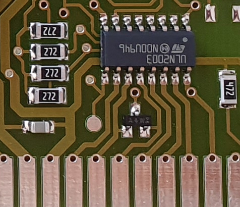
As the water inlet, detergent processing and heating cycle are controlled by individual relays that require an input voltage higher than 5 V, the PCB also includes a Texas Instruments ULN2003A Darlington transistor array.
The water level inside the washing machine’s drum is sensed by an SPX3078D analog pressure sensor manufactured by Motorola. This sensor basically consists of a silicon diaphragm, which is used to determine the applied pressure through a Wheatstone bridge circuit. The differential output voltage is then processed by an ELMOS E210.01C. Since ELMOS provides no public documentation on this component, its exact function is unclear. However, I strongly assume it contains an operational amplifier and possibly additional signal processing circuitry. One of the pins is connected to the microcontroller’s analog input port and provides a voltage proportional to the sensed pressure.

Most of the indicator LEDs on the PCB are multiplexed and wired to a Motorola MC14489DW LED driver, which offers an SPI interface for the microcontroller:
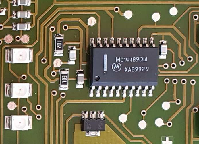
Upon detailed inspection of the LEDs on the right side of the board, one can see that the lowest LED is quite different from the rest of the group. Looking closer reveals that this is actually a combined red LED and infrared phototransistor. This is the optical PC interface, disguised as one of the indicator lights:

The LED is not part of the group of multiplexed indicator LEDs and is instead wired to a pair of transistors. An NPN transistor connects the microcontroller’s UART transmit pin to the light emitter, while the phototransistor is connected to the UART receive pin via a PNP transistor.
Power-up troubles#
To communicate with the EDPW board via the optical interface, the PCB has to be connected to an appropriate power supply. Luckily, the EDPW 206’s technical documentation includes the complete pinout of the board’s connectors:

However, simply supplying the board with 5 V from a lab power supply didn’t seem to have any effect. Taking a closer look at the pinout shows that the board also expects 20 V for the UC voltage, which is connected to the ULN2003A’s common-cathode node for the integrated flyback diodes. This voltage seems to be sensed by the microcontroller through a resistive divider. Unfortunately, even with those two voltages, the EDPW didn’t seem to turn on. Further investigation revealed that the board also requires an AC zero-crossing detection signal, referred to by the term Netznulldurchgang (NND) in German. This signal is generated by an optocoupler on the power electronics board, resulting in an alternating wave based on the line frequency. Supplying a 50 Hz square wave from a Pi Pico in place of this signal finally brought the EDPW to life:

While all basic functions of the EDPW seemed to work fine, including the program selection knob and the configuration buttons, I quickly noticed that the check intake and check drain indicators were flashing. Because the check intake LED also serves as the optical interface, this issue had to be resolved before any communication was possible. I initially assumed that the analog pressure sensor was giving some incorrect readings, but further investigations ruled out this theory. Instead, this issue was related to the missing relays that would normally be connected to the board. As it turns out, the microcontroller actually checks the presence of the prewash and main wash relays by sensing the voltage on the board’s relay outputs. When the relays are connected to UC on one side, the voltage at the transistor array’s collector pins is also equal to UC. Both the prewash and main wash outputs then go to a BAV70 common cathode double diode chip that is wired to the microcontroller:
Connecting a 10 kOhm resistor between the pin for the main wash relay and UC therefore stops the red LEDs from blinking. With this workaround in place, the EDPW board was now fully functional.
Dumping the EEPROM data#
Before reverse engineering the PC interface, it is worth taking a closer look at the EEPROM chip. Removing the chip from the PCB and soldering it to an SOIC adapter allows its contents to be read using a CH341A EEPROM programmer. It should be noted that the adapter can’t be plugged into the socket directly, as the pinout of the 93XXX chip differs from classic 25XXX EEPROMs that this programmer is designed for.


Reading the EEPROM contents with IMSProg revealed that only 42 bytes are actually used, with almost all remaining bytes set to ff, indicating erased or unused memory:
00000000  ff ff f0 ff ff ff cc fb  b0 55 fd ff ca ce f7 db
00000010  ff ff ff d3 fd ff ff ff  ff f7 fe f8 fe 11 f8 f8
00000020  f8 f8 f8 f8 f8 fa f8 f8  f8 63 ff ff ff ff ff ff
00000030  ff ff ff ff ff ff ff ff  ff ff ff ff ff ff ff ff
*
000001f0  ff ff ff ff ff ff ff ff  ff ff ff ff ff ff ff 00
To analyze how the stored data changes under different washing program settings and conditions, the EEPROM chip was soldered to the PCB again, while also attaching a logic analyzer to monitor the Microwire interface:


When the EDPW board is powered on, the microcontroller reads the first 42 bytes from the EEPROM. As soon as either the UC voltage or the zero-crossing signal are lost, the memory contents are written back to the EEPROM.

After trying out different washing programs and observing the changes to the individual bytes, the full EEPROM contents can be deciphered:
00000000  00 00 0f 00 00 00 33 04  4f aa 02 00 35 31 08 24
00000010  00 00 00 2c 02 00 00 00  00 08 01 07 01 ee 07 07
00000020  07 07 07 07 07 05 07 07  07 9c 00 00 00 00 00 00
00000030  00 00 00 00 00 00 00 00  00 00 00 00 00 00 00 00
*
000001f0  00 00 00 00 00 00 00 00  00 00 00 00 00 00 00 ff
All bytes are inverted before being written to the EEPROM by the microcontroller. The first 12 bytes store general information about the washing machine. As an example, this includes the currently running program and program phase (first and second byte) and the operating hours of the appliance (third and fourth byte). This section ends with a simple one byte checksum that is computed by summing the preceding bytes (modulo ff) and inverting the result.
The next group of bytes encodes the fixed washing machine configuration that can only be changed by entering the programming mode. Settings such as the water type and region code are stored in this section. Another checksum is appended to these bytes, again computed over all previous bytes.
Configuration options that are chosen during the normal operation of the machine (e.g. short, prewash, spin cycle RPM, etc.) are preserved in the subsequent bytes, stored separately for each individual washing program.
The last section is mostly empty, but most likely used to further customize the behavior of washing programs as part of the program correction mechanism. Selecting the Cottons 95 °C program for example causes the microcontroller to continuously read the byte at address 40 from the EEPROM, probably checking for some bit to be set. Despite some areas being unused or unclear, this EEPROM analysis provided some valuable insights into the internal operation of the EDPW.
Analyzing the firmware#
Returning to the PC interface, I wondered whether it might be possible to extract the microcontroller’s firmware to reverse engineer the diagnostic protocol. As previously noted, the firmware is stored in a mask ROM during manufacturing. Gaining access to the ROM’s contents would therefore require the chip to be decapped, which requires special equipment and practice that I don’t have. However, according to its manual, the Mitsubishi M37451 seems to feature multiple processor modes that might allow the ROM to be dumped:

The processor is running in single-chip mode by default, as the CNVSS pin is pulled to GND on the EDPW board. Connecting CNVSS to 5 V would cause the chip to enter microprocessor mode, loading the program code from external memory. This would in theory allow the embedded firmware to be dumped, but unfortunately, access to the internal ROM is blocked in this case, as specified in the manual. This restriction, likely implemented for security reasons, is not present for the memory expansion mode, but this processor mode can only be entered by writing to a register when running in single-chip mode.
Although techniques like fault injection or voltage glitching might bypass these limitations, I decided to continue the reverse engineering process without access to the firmware.
Reverse engineering the PC interface#
To communicate with the EDPW’s optical interface, I connected a USB-UART adapter directly to the microcontroller’s UART pins. Lacking a proper 5 V USB-UART adapter, I used an Arduino Uno clone just for its UART capabilities. As the optical interface seemed to be very sensitive to the infrared radiation of the sunlight, I decided to disconnect the phototransistor from the UART’s receive pin:

Now that the hardware was set up, it was time to focus on the actual serial communication. As might be expected, the interface doesn’t send any data on its own during normal operation, so its protocol must be based on a request-response scheme. However, figuring out the exact commands that need to be sent would be extremely difficult without any details about the protocol. It is often a good idea to look for similar protocols in this situation, which might provide some clues about the general command structure. After a more elaborate online search, I found a forum post (in German) describing the Miele@home interface, which is used to add remote control functionality to Miele appliances. It provides a detailed analysis of the Miele@home communication module and its serial protocol, including a full communication log between module and appliance.
The serial interface is initially configured for a data rate of 2400 baud with 8 data bits, 1 stop bit and no parity. After a short handshake sequence, the communication switches to a speed of 9600 baud. Considering that the Miele PC interface was introduced in 1996, it doesn’t seem unlikely that first implementations were limited to 2400 baud, which would explain why the communication begins at this baud rate. The messages sent by the module and the appliance are always either 5 bytes or 1 byte long, where a single 00 byte indicates the successful reception of a valid message by the receiving side. All 5-byte messages begin with a command byte, 2 unknown bytes and a single byte which seemingly indicates the expected length of the response payload. These messages end with a simple 8-bit checksum that is computed by summing the previous bytes, similar to the EEPROM checksum discussed in the last section.
With basic knowledge of the protocol, the first couple of messages can now be analyzed in further detail:
Module -> Appliance: 11 00 00 02 13
Appliance -> Module: 00
Appliance -> Module: fb 08 03
Module -> Appliance: 00
Module -> Appliance: 21 00 00 00 21
The handshake starts with command 11, expecting a response with a length of 02. The request is acknowledged by the appliance, which responds with fb 08. This response is likewise acknowledged by the module, which proceeds by sending the command 21. The rest of the handshake continues in a similar manner until the communication switches to 9600 baud. Could this be the same protocol that is used by the PC interface?
To confirm this assumption, I tried sending the initial 11 command via the USB-UART adapter:

Unfortunately, this didn’t lead to any response from the PC interface. At this point, I decided to take another look at the microcontroller’s datasheet, focusing on the UART section:

Assuming that the UART is indeed configured for 2400 baud, the only remaining options that can be configured are the number of data bits, stop bits and the parity mode. At this baud rate, a combination of 8 data bits and 1 stop bit would seem to be the most likely choice. However, since the communication is based on an optical interface, the parity bit might actually be used. And sure enough, configuring the USB-UART adapter for even parity and sending the same message again triggered a response from the EDPW:

In contrast to the Miele@home communication log, the payload of the response was a3 01 (419 in decimal) in this case. According to the technical documentation for the EDPW 206, this seems to be the so-called software ID of the board. Feeling relatively optimistic at this point, I tried transmitting the next handshake message, hoping to receive another response. However, upon sending the 21 command, the EDPW just answered with a single 02 byte. Trying other random commands also led to the same response, except for the 10 command which was acknowledged with 00. Sending a valid message with an incorrect checksum caused the EDPW to reply with 01.
Using a short Python script, I tested every single possible command, but none of the other commands received an acknowledgement from the EDPW. Nevertheless, even invalid commands had to be acknowledged by the PC before the EDPW would accept the next message:
PC -> EDPW: XX 00 00 02 CC
EDPW -> PC: 02
PC -> EDPW: 00

<continue with XX + 1>
At this point, the only two commands that triggered a positive response from the EDPW were 10 and 11. While messing around with command 11, I realized that the EDPW would not react to messages sent after this command unless the PC responded with its own 4-byte payload:
PC -> EDPW: 11 00 00 02 13
EDPW -> PC: 00 a3 01 a4
PC -> EDPW: 00
PC -> EDPW: 00 00 00 00

<next message can be sent>
However, changing the values of these 4 bytes didn’t seem to trigger another response from the EDPW. Wondering whether the handshake might require a certain sequence of commands, I modified the script to transmit command 11 before every iteration:
PC -> EDPW: 11 00 00 02 13
EDPW -> PC: 00 a3 01 a4
PC -> EDPW: 00
PC -> EDPW: 00 00 00 00
PC -> EDPW: XX 00 00 00 CC
EDPW -> PC: 02
PC -> EDPW: 00

<continue with XX + 1>
This revealed yet another valid command that was part of the handshake sequence: 20. However, that was apparently still not enough to successfully complete the handshake process. None of the commands I tried after this point yielded any meaningful response from the EDPW. The response to command 20 was always 00, no matter what parameter values I used for the message. After reading up on common diagnostic protocols from the 1990s, I came up with the following theory:
- Command
20is used to unlock the diagnostic interface, but requires a certain set of parameters (a secret key) - As part of the unlock sequence, command
11always has to be sent before20 - Upon reception of command
10, the diagnostic interface is locked again
But how can the secret key for the unlock command be determined? Assuming that the key is encoded in the two parameter bytes of the message, a simple brute-force approach would require up to 65536 tries to guess the key. However, without knowing whether the key was actually correctly guessed and which commands are unlocked if the correct key is provided, the total number of required attempts would increase significantly. Considering the interface’s low speed of 2400 baud, this strategy didn’t seem to be feasible at all.
Finding a different attack vector#
I decided to take a closer look at the microcontroller on the EDPW board in search of other attack vectors. As previously mentioned, the Mitsubishi M37451 is configured for single-chip mode, executing its firmware directly from the internal mask ROM. However, for the two other processor modes, the M37451 provides some additional output signals which can be used to control an external EEPROM. These signals are named WR, RD, R/W and SYNC, as can be seen in the bottom right corner of the microcontroller’s pinout:

According to the datasheet, the SYNC signal is high while the microcontroller is fetching an operation code from its memory. Reading from the data bus sets RD high, while writing to an external component sets WR high. The bus transfer direction is also indicated by a combined R/W signal, which is high during bus reads and low during bus writes.
One would expect these signals to be disabled when the microcontroller operates in single-chip mode, right? Well, to my surprise, attaching a logic analyzer to the SYNC pin actually showed significant activity:

It turned out that all of the data bus signals are enabled, even in single-chip mode when the internal mask ROM is used. Could this SYNC signal be used to observe the program execution while receiving a diagnostic message via the PC interface? Yes, in fact the whole message processing can be seen in the logic analyzer trace:

Zooming in slightly after the stop bit shows the actual UART interrupt service routine that is being executed:

When sending an invalid diagnostic message instead, the microcontroller seems to return from the interrupt routine much earlier:

The length of the interrupt routine can therefore be used to distinguish between valid and invalid messages.
Leaking the secret key#
With these observations in mind, it should be possible to figure out the secret parameters for the unlock command. The unlock command likely looks something like this in pseudocode:
fn handle_cmd_unlock(param1: u8, param2: u8) {
    if (param1 != UNLOCK_KEY1)
        return;

    if (param2 != UNLOCK_KEY2)
        return;

    unlock_interface();
}
Therefore, guessing the correct value for the first parameter should lead to a slightly longer execution time of the interrupt routine. This same procedure can then be repeated for the second parameter, while keeping the correct value for the first parameter to discover the correct unlock message. Unlike a full brute-force approach, this approach only takes 512 tries at maximum. Each unlock attempt then consists of the following steps:
- Send command
11to the PC interface as the first part of the unlock sequence - Start logic analyzer capture, triggering on the falling edge of the UART receive signal
- Transmit command
20with the chosen parameter values - Decode the recorded trace and convert the SYNC sequence into a string of 1’s and 0’s
As before, this process is automated using a Python script and the sigrok-cli tool. As part of the decoding process, the script samples the SYNC signal on every falling edge of the microcontroller’s clock output signal:

The recorded SYNC trace is thereby turned into a long bit string:
10100101001010100010101000001000101000101000010000100101000100100100001000010010100010001010001001010100001010000100001010101000101010001010001010100010100010101000101000101010100101001010001000100000100101010101010010101010100010000101010001010101000100000100010001000100010100001000100101010000010010100010100010101000001001000100010100001000100000100010000010000010001000101000101000
As the microcontroller is constantly executing instructions, the actual start and end of the interrupt routine are always at a different position in the bit string. It is hard to distinguish between this routine and instructions that run before or after the actual interrupt. To find the boundaries of the routine, I defined two bit patterns that are common for every bit string:
Start pattern: 10100101001010100010101000
End   pattern: 10000010001000101000101000
Using these patterns, the actual payload of the SYNC trace can be determined:
10100101001010100010101000001000101000101000010000100101000100100100001000010010100010001010001001010100001010000100001010101000101010001010001010100010100010101000101000101010100101001010001000100000100101010101010010101010100010000101010001010101000100000100010001000100010100001000100101010000010010100010100010101000001001000100010100001000100000100010000010000010001000101000101000
This result then allows measuring the interrupt routine’s execution time. A change in bit stream length therefore clearly indicates a correct unlock parameter. The Python script can now be used to capture the bit strings for all possible values of the first parameter:
[20, 00, 00, 00]: 00100...10001000101000010001000001000100000
...
[20, eb, 00, 00]: 00100...10001000101000010001000001000100000
[20, ec, 00, 00]: 00100...10001000101000010001000001000100000
[20, ed, 00, 00]: 00100...10001000101000010001000001000100000
[20, ee, 00, 00]: 00100...100010100100010001010000100010001000001000100000
[20, ef, 00, 00]: 00100...10001000101000010001000001000100000
[20, f0, 00, 00]: 00100...10001000101000010001000001000100000
[20, f1, 00, 00]: 00100...10001000101000010001000001000100000
...
[20, ff, 00, 00]: 00100...10001000101000010001000001000100000
And there it is: The correct first parameter seems to be ee. This procedure is now repeated for the second parameter:
[20, ee, 00, 00]: 00100...00010001010000100010001000001000100000
...
[20, ee, b1, 00]: 00100...00010001010000100010001000001000100000
[20, ee, b2, 00]: 00100...00010001010000100010001000001000100000
[20, ee, b3, 00]: 00100...00010001010000100010001000001000100000
[20, ee, b4, 00]: 00100...000101000101010100001000100010001000001000100000
[20, ee, b5, 00]: 00100...00010001010000100010001000001000100000
[20, ee, b6, 00]: 00100...00010001010000100010001000001000100000
[20, ee, b7, 00]: 00100...00010001010000100010001000001000100000
...
[20, ee, ff, 00]: 00100...00010001010000100010001000001000100000
A few seconds later, the correct parameter combination for the unlock message is identified: ee, b4.
Unlocking the PC interface#
The full functionality of the diagnostic interface can now be enabled by completing the unlock sequence:
PC -> EDPW: 11 00 00 02 13
EDPW -> PC: 00 a3 01 a4
PC -> EDPW: 00
PC -> EDPW: 00 00 00 00
PC -> EDPW: 20 ee b4 00 c2
EDPW -> PC: 00
PC -> EDPW: 00
But what did this sequence actually do? Re-testing the command set reveals the presence of commands 30, 31 and 32, which are now successfully acknowledged by the EDPW.
While messing around with these new commands, I discovered that sending the command 31 causes the EDPW to respond with a maximum of 4 bytes, depending on the requested response length of the message. However, all returned bytes were zero, regardless of the parameter values:
PC -> EDPW: 31 00 00 04 35
EDPW -> PC: 00
EDPW -> PC: 00 00 00 00 00
Upon further inspection of the EDPW board, I noticed that I forgot to supply power to the EEPROM chip. Sending the command again now resulted in the following response:
PC -> EDPW: 31 00 00 04 35
EDPW -> PC: 00
EDPW -> PC: 00 00 0f 00 0f
Trying different parameter values resulted in varying responses from the EDPW, revealing that command 31 reads the (inverted) EEPROM data starting at the specified offset.
Moving on to command 30, I quickly noticed that its behavior closely followed the EEPROM read command. However, its response didn’t appear to depend on the presence of the EEPROM chip. Reading the first 256 bytes using this command resulted in the following data:
00000000  00 00 00 00 00 00 33 00  4f 8a 02 00 35 33 02 01
00000010  00 05 00 89 ff ff ff ff  00 08 01 07 01 ee 05 07
00000020  07 07 07 07 07 05 07 07  04 9c fe 03 02 00 00 00
00000030  44 00 00 00 00 00 0a 00  83 00 00 00 00 00 00 00
00000040  00 00 ff ff fd 00 00 f8  44 00 00 00 00 00 26 00
00000050  e3 db 4a 00 00 00 04 20  80 3f 00 00 00 30 00 00
00000060  00 00 00 00 00 00 00 00  40 00 02 00 00 00 00 00
00000070  00 00 00 00 00 00 00 00  00 00 00 00 00 00 00 00
00000080  00 00 00 00 20 00 00 00  54 01 00 00 00 00 00 00
00000090  00 ff ff 00 ff ff 00 5c  43 00 00 00 00 00 00 00
000000a0  05 20 18 00 01 00 18 00  00 ff ff 07 06 02 2c 06
000000b0  02 00 00 00 00 05 30 b4  00 10 f8 00 10 f8 00 08
000000c0  00 00 00 00 00 00 00 00  00 00 00 00 00 00 00 00
000000d0  3e ce 38 c4 00 fb b6 e9  9b 00 00 ff 02 fd 70 90
000000e0  00 00 6e 14 04 01 24 84  b8 f2 81 84 ff 00 00 03
000000f0  cc 32 c4 09 64 07 c4 09  9e 5c ff ff 00 21 e8 1c
Hmm, could this be the internal memory of the microcontroller? To verify this, I consulted the memory map of the Mitsubishi M37451:

The area marked as not used in the diagram ranges from address c0 to cf. Assuming that these bytes were zero, this would match with the response data from command 30. Another memory area to check would be the SFR region. Knowing that the baud rate generator was configured for a baud rate of 2400, the BRG register at address ea would have to be set to 81. This value could also be found in the previous response. The rest of the memory contents were part of the RAM region. This confirmed that command 30 reads memory contents based on the provided address parameters.
Dumping the full memory contents#
After some quick modifications to the Python script, I managed to dump the complete memory contents from the microcontroller:
This whole process took around half an hour due to the low baud rate of the PC interface. Taking a closer look at the memory dump reveals that it actually contains the full internal mask ROM contents of the microcontroller:
0000a000  1f d4 2a 90 04 2f d4 80  02 3f d4 0f d4 88 d0 f0
0000a010  60 2f d5 0f d5 ef d3 ff  d2 3f d4 1f d4 0f d4 1f
0000a020  d4 ef d2 0f d4 1f d4 2f  d4 0f d4 a0 02 20 00 a0
0000a030  a0 08 a5 4b 20 00 a0 1f  d4 60 85 4b a9 80 20 11
<snip>
0000ffd0  ff ff ff ff ff ff ff ff  ff ff 30 11 00 a3 01 03
0000ffe0  e9 b1 e9 b1 62 d7 43 d7  4a cd e9 b1 e9 b1 13 cd
0000fff0  d9 e2 71 b1 e9 b1 f2 b0  e9 b1 e9 b1 e9 b1 28 b4
And there you have it! A full firmware dump of the Mitsubishi M37451 on the Miele EDPW 206 board.
While this blog post about the Miele PC interface protocol is far from complete, I think it’s time to wrap things up for now. The full reverse engineering of the protocol will have to wait until next time, where I’ll dive into a detailed analysis of the firmware.
Thanks for reading!